AN-014 – Using the 1600-100RTD Sensor
The 1600-100RTD sensor sold by Arroyo Instruments is a very small form factor RTD sensor. The sensor head has three wire leads existing the device, and a question often asked is: “how do I wire this into my system?”
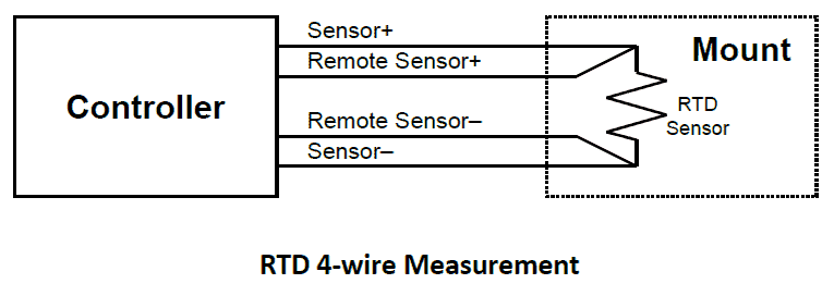
RTD sensors are low resistance devices whose accuracy can be significantly impacted by additional resistance losses from long cables and connector interfaces. Resistance measurements are made by driving a small current (known as the “bias” current) through the device and measuring the resulting voltage that develops across the device. Using Ohm’s Law (V = I * R), if the bias current and voltage are known, the resistance can be calculated. However, this bias current also develops voltage across the resistances in the cable and the connectors. In a single pair system, the total resistance is that of the sensor, cable, and connector resistances combined, with the cable and connector resistances causing an offset in measurement.

To mitigate this error, a 4-wire, or Kelvin, measurement is employed. In this configuration, one pair of wires is used to drive the bias current through the device, and a second pair, connected as closely as possible to the sensor, measures the voltage. Because the second pair is not carrying any current, the resistance of the cable and connectors that make up the second pair do not affect the voltage measurement. In this setup, the voltage across the sensor can be accurately measured.
However, the 1600-100RTD sensor only has three wires, so how do you connect it to the controller to make the best possible measurement?
The answer is to convert the three-wire configuration of the 1600-100RTD sensor to a 4-wire connection as early as possible in the measurement path. The two white wires are connected to one side of the RTD, while the red wire is connected to the other side. By keeping the RTD wires reasonably short and connect them into the 4-wire measurement before any connectors, the only error is the resistance of the short length of red wire, which adds a very, very small error into the measurement, well below the accuracy of the measurement system.

In the drawing above, the RTD sensor is shown with the single red white wires (shown in black) exiting the sensor. Use short lead lengths between the RTD head and the connection to the DB connector where it’s converted to a 4-wire measurement… then the rest of the way back to the instrument is in 4-wire mode.
USING THE RTD SENSOR WITH MOUNTS SUPPORTING EXTERNAL SENSOR INPUT
If you plan to use the 1600-100RTD sensor as an external sensor input into Arroyo mounts that support the EXT SENS input (for example, the 207, 274, 284, 285, and 286 mounts support this feature), it is recommended that you wire both white wires into one input, and the red wire into the other input. The mount converts the sensor input into a 4-wire measurement inside the mount.
RTD SENSORS ARE NOT POLARIZED
It does not matter to which input (Sensor+ or Sensor–) the red or white wires are connected. RTD sensors are resistive devices and have no polarity, so while the drawing above shows the red wire connected to Sensor–, that is only for illustration.