WHAT IS A GROUND LOOP?
A ground loop occurs when a system of electronic devices has two or more fully independent paths to earth ground. Ground currents flow through this loop, inducing voltages into the system. This can be a serious problem when one or more of the paths goes through the control electronics, which can interfere with proper operation of the system and potentially damage your laser.
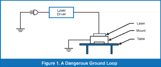
In a laser system, a common scenario for a ground loop occurs when the anode or cathode of the laser is connected to the case of the laser package, which is then connected to earth ground through the laser mounting system. If the laser driver is also connected to earth ground, a ground loop is formed through the laser and control electronics.
Another common place to encounter a ground loop is the connection between a function generator and the laser driver. You might use a function generator in order to modulate or control the laser intensity. Many function generators connect the signal output ground to earth ground. When the driver electronics are also connected to earth ground, then the connection between the two devices produces a ground loop.
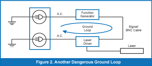
In both of these scenarios, your devices have two independent paths to ground, both through the critical electronics that control the current flow to the laser.
SOME GROUND LOOPS ARE HARMLESS
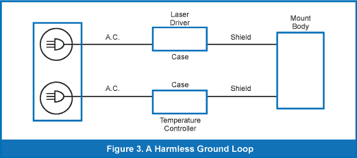
The ultimate question you should ask yourself: Is there a path through my laser or control electronics? If there is not, then the ground loop may be benign. An example of a harmless ground loop would be one that travels exclusively through the mount and cabling, or cable shielding. While these components may be connected into a ground loop, they do not create a hazard because there is no path through your electronics or through your laser.
THE DANGER OF A GROUND LOOP
A ground loop is essentially a continuous loop that travels through your instruments. This loop is susceptible to noise that exists on the same electrical circuit, such as those generated by fluorescent lights, ground currents from other power supplies, soldering irons or other devices that cycle on and off, etc.
The primary risk from a ground loop is that it may expose your laser or control electronics to an uncontrolled or unexpected source of current or voltage. This means potential damage to your laser. It also means potential danger to you and your personnel, as the laser may produce light unpredictably or at unexpected levels.
A ground loop may become dangerous in two ways. First, it may induce a signal into the modulation input port of the laser driver, which then produces a current spike in the laser. The modulation input port directly controls the set point of the laser, so it directly affects the amount of current entering the laser.
Second, a ground loop may discharge ground current into the laser package that was produced by another device also grounded on the same electrical circuit. This second avenue can be deceptive because you may not see a current spike immediately upon connecting the system. Particularly in a laboratory environment where multiple devices connect to the same electrical circuit, another device may be connected or switched on without your knowledge. In the presence of a ground loop, the change in the ground circuit may begin to affect your electronics or your laser.
WHERE CAN GROUND LOOPS OCCUR?
You may find a ground loop in any setting where multiple, grounded devices are connected together. Two common examples are given above, though it may occur elsewhere. A ground loop might also form between the laser and the photodiode. Especially if a photodiode or another sensor were located apart from the laser package, perhaps on another part of the optical table, then you would have the potential for a ground loop.
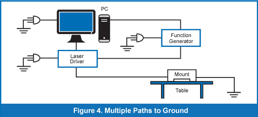
You may inadvertently produce a ground loop by employing a USB interface. Since your computer will certainly be grounded, any instrument connected to the laser driver and to your computer via USB interface may produce a ground loop. Figure 4 shows such a scenario.
Laboratory settings often create a perfect storm for ground loops that can cause damage to a laser package. Particularly in an educational or university environment, devices are connected and disconnected often. Students pass through the laboratory on a regular basis and may not be aware of the potential risk. Because of these constantly changing circumstances, eliminating the possibility of a ground loop in a laboratory is paramount.
To identify a possible ground loop, you must take into account all the components of your laser system, including the:
- laser driver
- function generator
- computer interfaces
- optical table
- mounting fixtures
- sensors
Each of these components represents another possible path to earth ground.
LABORATORY METHODS FOR BREAKING A GROUND LOOP
In any case, careful characterization of your power supply is of the utmost importance to reduce the risk of laser damage. Ultimately, your best option may be to use a laser diode driver. A laser driver will include a variety of safeguards specific to operating a laser. Even the most inexpensive laser driver will offer superior protection, higher accuracy, and better performance than a bench power supply.
ELECTRICAL INSULATORS
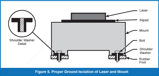
If the ground loop has a potential path through certain mounting hardware – such as the fasteners that connect your laser mount to a table – then add an electrical insulator. Placing a shoulder washer between the fastener and the laser mount, as shown in Figure 5, will break the ground loop. Verify that no other part of the laser mount touches the table.
SILLPAD
Another alternative is to break the ground loop directly at the interface between the laser diode and the thermal heat sink. There are materials available which are electrically insulative and thermally conductive. One such product is called Sillpad. Applying a layer of such a material between the laser diode and the heat sink allows you to break the ground path that travels through the heatsink while maintaining the correct level of thermal management.
GROUND LIFT PLUGS
There are circumstances where the only feasible location to break a ground loop is at the outlet. In these circumstances, you may consider using a ground lift plug. This will allow you to connect a three prong electrical cable to a standard outlet without connecting to earth ground.
Warning: With this approach, you should be aware that you may be creating a potentially hazardous condition that may result in an electrical shock. The earth ground connection is responsible for dissipating the charge that would otherwise build up inside an electronic device. Removing the connection to earth ground may allow this charge to build up sufficiently to transmit an electrical shock to you while you operate the device.
HARDWARE METHODS FOR BREAKING A GROUND LOOP
There are circumstances where the only feasible location to break a ground loop is at the outlet. In these circumstances, you may consider using a ground lift plug. This will allow you to connect a three-prong electrical cable to a standard outlet without connecting to earth ground.
The best way to address a ground loop in your laser system is within the electronic equipment itself. At the hardware level, a good laser diode driver will isolate the various inputs from the control circuitry so that a ground loop cannot pass through the laser. The components of the laser driver that should be isolated include:
- USB connectors
- RS-232 connectors
- Modulation input ports
- Thermal input ports
- Control circuitry
To achieve this level of segregation inside the device, a well-built laser diode driver uses optical or electronic isolation technology. Isolation allows the device to pass an analog signal from one location to another without a continuous electrical connection and without any loss of fidelity.
The risk of an unpredictable electrical event, caused by a ground loop, should be addressed as thoroughly as possible. Working in a laboratory, there are a number of practical methods that may help to address a ground loop. In a laser system, the preferred method for addressing a ground loop to employ optical isolation within the laser driver, preventing any possibility of a ground loop that passes through the easily damaged laser diode.
How to Find and Correct Dangerous Group Loops in Your Laser System (PDF Version)